 werMake
The Layers of Industrial Automation
By Daniel Patterson
Industrial Automation has a nasty reputation of requiring knowledge that is both a mile wide and mile deep, partially because of the sheer number of legacy practices and techniques that have made it what it is today, and partially because of the vast advances that have been made outside of its direct purview, but which are being directly applied to improving productivity and overall efficiency.
This article provides a quick outline of all of the layers of industrial technology, with a short discussion at each level, beginning at the physical world and becoming increasingly conceptual, in a kind of signal-to-ROS (Robot Operating System) progression.
Physical World
At the foundation of all systems is the physical world; a domain composed of mechanical, electrical, fluidic, pneumatic, photonic, thermal, and organic phenomena, each governed by its own physical laws and dynamic behaviors.
The physical world is the origin point for all robotic interaction. This layer is where real forces act, and where sensors and actuators must ultimately operate. Below are examples of how physical behaviors manifest in real-world systems:
A lever balancing upon a fulcrum.
A rotating motor shaft.
A magnetic or optical encoder ambiently reacting to a part of the turning shaft.
Sensors - Perceiving the World
Sensors are interfaces that convert physical phenomena into measurable electrical signals. They allow systems to perceive the state of the environment or themselves, translating motion, light, pressure, temperature, force, or other analog and digital attributes into data.
Below are common categories of what sensors may detect:
Motion. Rotary encoder, IMU.
Force. Strain gauge, load cell.
Light. Camera, photodiode, lidar.
Environment. Temperature sensor, gas sensor, humidity probe.
Actuators - Influencing the World
Actuators convert electrical or digital commands into physical action. They enable systems to affect their surroundings by creating motion, force, light, sound, or other physical effects through mechanical, fluidic, or electromagnetic means.
Actuators are the system's way of affecting change in the physical world. They convert digital or electrical control signals into physical movement, force, light, heat, or other tangible effects. While sensors read the world, actuators write to it. Below are common types of actuators categorized by what they influence:
Motion. Servo motor, stepper, hydraulic piston.
Force. Solenoid, electric brake.
Sound and Vibration. Speaker, haptic motor.
Light. LED array, laser.
Thermal. Heater element, Peltier cooler.
Electrical Signal
The electrical signal serves as the immediate and tangible expression of a physical phenomenon in the language of voltage, current, or timing. It is the first translation from the real world into a form that electronic systems can detect, measure, or control.
Once a physical phenomenon is detected by a sensor, it is transduced into an electrical signal; typically, voltage or current. This signal may be analog (continuous) or digital (discrete), representing the magnitude, frequency, or timing of the observed event.
These are some examples of electrical signals:
Analog. 0–5V representing temperature.
Digital. High/Low pulses from an encoder.
PWM. A square wave where duty cycle encodes value (e.g., servo position).
Differential pairs, like twisted pair copper wires: Used for noise immunity (e.g., RS-485, CAN).
Signal Interface - ADC, DAC, Digital I/O, Encoder, and Decoder
This layer translates between the Voltage / Timing and Number / Line Logic levels, or between Analog reality and a Digital model. It's critical because the microcontroller can't see or act on anything until the signal is converted.
These interfaces act as the bridge between continuous electrical signals and discrete computational values. They digitize analog input, generate analog output, or read/write digital states. In the case of encoders, they also track changes over time to infer motion or position.
The following subsections briefly describe the various parts of this layer.
Analog-to-Digital Converter (ADC)
The ADC is responsible for converting analog electrical signals into discrete digital numeric values. The following are some highlights of ADC usage.
They can convert a voltage (e.g., 0–3.3V) into a numeric value (e.g., 0–4095 for a 12-bit ADC).
They are often used for sensing applications like thermistors, potentiometers, and pressure sensors.
Key factors to consider are resolution, sampling rate, reference voltage.
Digital-to-Analog Converter (DAC)
The DAC converts digital numeric values into approximate analog values. The following are some of the highlights of a DAC.
They convert a numeric value into an analog voltage.
They can be used to drive analog actuators (e.g., servos, variable valve controllers, audio).
Digital I/O (GPIO)
General-Purpose Input / Output, or GPIO, is a lightly protected access point directly from the outside world to pins on a microcontroller board. Unless otherwise, noted, GPIO signals are always expected to be in pre-conditioned digital format. The following are some GPIO highlights.
They are simple binary pins (HIGH/LOW), sometimes with Hi-Z states available.
They are typically used for switches, LEDs, relays, and trigger signals.
Encoder Interface
An Encoder Interface is a crucial component in motion control and automation systems, responsible for interpreting signals from an encoder, which is a sensor measuring rotational or linear movement. These are some of the highlights of encoder interfaces:
They are hardware timers or counters that track rising and falling edges of quadrature signals (A/B, sometimes Index).
They can detect direction and speed with high precision.
They are sometimes implemented in dedicated peripherals (e.g., STM32's TIMx encoders).
Microcontroller / Driver Board
The microcontroller or driver board acts as the local intelligence and control hub at the edge of a system. It interprets incoming electrical signals from sensors, executes programmed logic, and issues precise electrical outputs to drive actuators or communicate with higher-level systems.
It is the translator between the analog world and digital logic, and the executor of small, fast, and deterministic decisions, often having millisecond or microsecond precision. While not distinctly 'aware' in any cognitive sense, it embodies intent by enacting control strategies in real-time.
The microcontroller or its driver board are where physics meets logic, and rules meet reality. Unlike general-purpose computers, they operate under tight timing, power, and resource constraints, yet must respond with speed, precision, and reliability.
Functional Role
Functionally, the microcontroller board performs these activities.
It reads digitized sensor input (via ADC, digital I/O, communication bus).
It processes data using algorithms or control loops (PID, filtering, decision trees).
It drives actuators (via PWM, DAC, GPIO, motor controllers).
It communicates with external systems (e.g., via UART, SPI, I2C, CAN, or USB).
It maintains state across cycles, stores calibration and configuration data.
It schedules tasks in real-time or pseudo-real-time fashion (using timers or interrupts).
Basic Microcontroller Architecture
A microcontroller is typically built from common building blocks, tied together through a system bus, and controlled by registers.
| Element | Description |
|---|---|
| Processor Core | Executes instructions (e.g., ARM Cortex-M). |
| Flash Memory | Stores program code. |
| Static / Dynamic RAM | Stores variables, stack, buffers. |
| Clock System | Drives timing (e.g., 8 MHz internal clock or external crystal). |
| GPIO / Digital I/O | Interface to buttons, LEDs, switches, etc. |
| ADC / DAC | Analog input/output. |
| Timers and Counters | Generate PWM, time events, measure signal timing. |
| Communication Interfaces | UART, SPI, I2C, CAN, USB. |
| Interrupt Controller | Handles asynchronous events (e.g., pin change, timer overflow). |
Example Functions at the Firmware Level
Here are a few realistic and common microcontroller-level tasks.
Read a Temperature Sensor
int adc_value = read_adc_channel(0);
float temperature = convert_to_celsius(adc_value);
Control a Motor with PWM
set_pwm_duty_cycle(MOTOR_CHANNEL, 75); // 75% duty cycle
Set an LED on a GPIO Pin
gpio_write(PIN_LED, HIGH);
Respond to a Button Press via Interrupt
ISR(PIN_BUTTON_INTERRUPT)
{
 toggle_led();
}
Send Received Sensor Data Over UART
uart_write("Temp: ");
uart_write_float(temperature);
Examples of Microcontrollers and Driver Boards
| Microcontroller | Notes |
|---|---|
| STM32F103 | Widely used ARM Cortex-M3 with rich peripherals. |
| ATmega328P | 8-bit chip used in Arduino Uno. |
| ESP32 | Wi-Fi + Bluetooth + dual-core MCU. |
| TI TMS320 | DSP-class controller for real-time motor control. |
| Raspberry Pi Pico (RP2040) | Affordable dual-core MCU for education & prototyping. |
Embedded Firmware and Real-Time Loop
Embedded firmware is software that directly controls the microcontroller or driver board. It reads inputs, executes control logic, and generates outputs, all in tight synchrony with the real-world timing demands of the system. The real-time loop is the cyclic structure or scheduler that ensures tasks are performed consistently, predictably, and most often, deterministically.
Firmware is the embodiment of intention, implemented as a set of small, rigid rules that create order out of chaotic physical inputs. In systems where milliseconds matter, it is a miniature governing body that never sleeps, never slows, and must always respond on time.
At this level, cause and effect must align with clock ticks, not human intuition. There's no GUI, no OS abstraction, just time, state, and control.
Function Role
These are some examples of the functional activities taking place at the embedded firmware layer.
Poll or respond to sensor inputs.
Update internal models or calculations (e.g., filtering, PID control).
Drive actuators based on system state.
Schedule tasks using a loop or interrupt-driven design.
Handle communication with other microcontrollers, PCs, or ROS 2 hosts.
Ensure timing guarantees (e.g., execute every 1ms).
Manage system safety or emergency conditions (watchdogs, limit detection).
Real-Time Loop Architectures
The following are some examples of the kinds of logic that can be found operating within the real-time loop.
Super Loop (Baremetal)
while(1)
{
 read_sensors();
 compute_control();
 drive_actuators();
 delay_until_next_cycle();
}
Interrupt-Driven
void loop()
{
 // Wait here — let interrupts run the show
}
ISR(TIMER1_COMPA_vect)
{
 // Execute every 1ms
 read_sensor();
 update_pid();
 write_pwm();
}
RTOS-based (Real-Time Operating System)
// Pseudocode for FreeRTOS-style tasks
Task1: Sensor_Read → every 5 ms
Task2: Control_Loop → every 10 ms
Task3: Comm_Send → every 20 ms
PID Controller Function
int pid_compute(int target, int actual)
{
 int error = target - actual;
 integral += error \* dt;
 derivative = (error - last_error) / dt;
 last_error = error;
 return (kp \* error) + (ki \* integral) + (kd \* derivative);
}
Watchdog Reset Logic
while(1)
{
 refresh_watchdog();
 // normal operation
}
Device Communication Protocol
The communication protocol layer is responsible for reliably transmitting data between the microcontroller and external systems. It ensures that measured values, control signals, and configuration commands can move across electrical interfaces and be correctly interpreted, even across different platforms and timing domains.
This layer is the voice and ears of an embedded system and is not concerned with why a specific detailed value is important, but wholly dedicated to making sure it gets there faithfully and efficiently. It speaks in structured, repeatable phrases, encoding meaning in symbols over wires, voltages, and time.
This layer turns electrons into language, and structure into motion.
Functional Role
The functional activities at this layer of operation include the following.
Package data into frames or messages according to protocol rules.
Transmit data over hardware buses (serial, CAN, SPI, etc.).
Receive and validate messages (checksums, headers, sequence IDs).
Implement error handling (retries, timeouts, acknowledgments).
Support addressing or arbitration when multiple nodes are on the same bus.
Synchronize timing-sensitive systems (e.g., distributed motor control)
Common Protocols and Physical Layers
Listed below are a tiny set of possible protocols that might be spoken at the protocol level.
| Protocol | Physical Layer | Use Case |
|---|---|---|
| UART / RS-232 | Point-to-point serial | Simple, human-readable, great for debugging |
| SPI | High-speed short distance | Peripheral buses (sensors, displays) |
| I2C | Multi-device bus | Configuration or sensor buses |
| CAN / CANopen | Differential bus, multi-drop | Robust for automotive and industrial nodes |
| EtherCAT | Ethernet-based, real-time | Precision motion control |
| USB | Host/device serial | PC communication or firmware updates |
Typical Protocol Stack Layers
Described in the following table are a few of the protocol stack layers and their contexts.
| Layer | Description |
|---|---|
| Application | Information or what data actually means in the end use. (e.g., "Temperature = 32.5°C"). |
| Protocol Layer | Structure and formatting (e.g., start byte, ID, checksum). |
| Physical Layer | Electrical signals over wire (e.g., 5V TTL, differential pairs). |
Example Encoded Data Formats
The following list of examples illustrates a few types of data formats that exist.
UART Message (Custom Binary Protocol)
[0xAA] [0x01] [0x02] [0xA7]
| | | |- Checksum
| | |- Payload
| |- ID
|- Header
CAN Frame (11-bit ID)
ID: 0x105
Data: [0x03, 0xFF, 0x2C, 0x00]
Modbus RTU Message
[Slave Addr] [Function Code] [Register Addr] [CRC]
Example Microcontroller Code
Microcontroller code written for the protocol level might resemble the following example.
void send_temp(float temperature)
{
 uint8_t buffer[5];
 buffer[0] = 0xAA; // Header
 buffer[1] = 0x01; // Msg ID
 int temp_int = (int)(temperature \* 10);
 buffer[2] = temp_int & 0xFF;
 buffer[3] = (temp_int >> 8) & 0xFF;
 buffer[4] = calc_checksum(buffer, 4);
 uart_write_bytes(buffer, 5);
}
Driver Software on Host
Driver software on the host receives and interprets data from communication protocols like UART, CAN, and USB, transforming raw device-level messages into structured, usable information. It provides software abstraction of hardware devices, allowing higher-level programs, like ROS 2 nodes, for example, to interact with real-world data through clean APIs or message interfaces.
This layer is the translator and mediator between machine-level data and human-scale meaning. It knows both the low-level structure of the data and the high-level purpose of the system. Its job is not to control hardware directly, but to represent it accurately, accessibly, and reliably to the rest of the software world.
It is the veritable "ghost in the wire"; invisible when working properly, but essential to everything above.
Function Role
The following are some of the activities this layer is responsible for.
Accessing physical devices (e.g., /dev/ttyUSB0, /dev/can0).
Parsing communication protocols (custom binary, CANopen, Modbus, etc.).
Validating and decoding messages (headers, checksums, field mapping).
Packaging data into usable data structures (e.g., C++ classes, Python dicts).
Exposing interfaces via API, CLI, or a publisher/subscriber mechanism.
Logging data, handling errors, and maintaining state.
Optionally, re-encoding and sending commands back to the device.
Common Implementation Forms
Some of the most common forms of implementation are highlighted in this table.
| Type | Description | Example |
|---|---|---|
| C/C++ Shared Library | High-performance low-level access | libserial, socketcan, libmodbus |
| Python Driver | Rapid prototyping, accessible | PySerial, python-can, custom Python scripts |
| Kernel Module (rare) | Tight hardware integration | USB drivers, custom PCIe cards |
| ROS 2 Node Wrappers | For publishing to topics/services | A bridge node that reads from /dev/ttyUSB0 and publishes /sensor/temp |
Example Workflow (Serial Protocol)
The following basic workflow illustrates the type of interactivity you might find at this level.
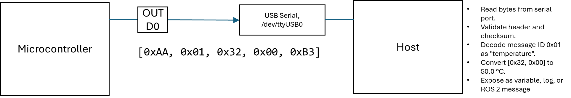
Example Code (Python, Serial Parser)
This example illustrates code you might find on a serial port reader on the host PC.
import serial;
def read_packet(port):
 data = port.read(5);
 if data[0] != 0xAA:
  return None;
 if not valid_checksum(data):
  return None;
 if data[1] == 0x01:
  raw_temp = data[2] | (data[3] << 8);
  return raw_temp / 10.0; \# Temperature in °C
 return None;
ser = serial.Serial('/dev/ttyUSB0', 115200);
while True:
 temp = read_packet(ser);
 if temp is not None:
  print(f"Temperature: {temp:.1f}°C");
Diagnostic Tools Often Used Here
There are a vast number of software applications and systems that can be used to develop and troubleshoot communications at the protocol layer. Listed below are a few of them.
Device identification.
dmesg,ls /dev/tty*,udevadm info.Serial debugging.
minicom,screen,cutecom.CAN bus testing.
candump,cansend.USB, EtherCAT, or Modbus over TCP inspection.
tcpdump,wireshark.Custom logging scripts for protocol capture.
Middleware Layer - ROS2
The ROS 2 middleware layer is the infrastructure that enables structured communication between software components in a robotic system. It transports data from producers, like drivers, and sensors, to consumers, like controllers, planners, and visualizers, using publisher-subscriber messaging, services, and actions over a standardized communication backbone. In other words, it turns isolated pieces of code into a coherent distributed system.
The middleware is not about the content of data, but the reliable, flexible, and timely delivery of it, across nodes, machines, and networks. It is a scaffold for autonomy; decoupling computation from physical location, decoupling when something is produced from when it's needed.
Middleware enables systems to be composed, distributed, and scaled, which is a key enabler for modular, reusable software.
Functional Role
The middleware layer provides a set of key communication primitives and services that allow independent nodes to interact. Below are some of its main functions:
It facilitates communication using Topics for data streaming, Services for synchronous request/response, and Actions for long-running tasks with feedback.
It encodes messages using type-safe schemas (e.g., .msg, .srv, .action files).
It abstracts transport layer (DDS by default, TCP/UDP-based).
It handles serialization, addressing, discovery, and QoS (Quality of Service).
It provides time synchronization, logging, diagnostics, and introspection.
Basic Architecture Flow
The following illustrates how data typically flows between ROS 2 nodes using the middleware infrastructure:
| Element | Activity | Sample Target |
|---|---|---|
| Driver Node | Publishes | /sensor/temperature [std_msgs/Float32] |
| Controller Node | Subscribes | /sensor/temperature |
| Navigation Node | Sends Action Goal | /move_base |
| Motor Driver Node | Executes Action | /move_base, sends feedback |
Behind the scenes, keep in mind:
The ROS 2 middleware (usually DDS) handles where, when, and how the data flows.
Nodes don't know about each other's internal structure. They only know the interface contracts.
Example Code (Publishing a ROS 2 Topic, Python)
Here's a simple example of how a node might publish temperature data in ROS 2 using Python:
import rclpy;
from std_msgs.msg import Float32;
def main():
 rclpy.init();
 node = rclpy.create_node('temp_node');
 pub = node.create_publisher(Float32, 'sensor/temperature', 10);
 msg = Float32();
 msg.data = 26.5;
 pub.publish(msg);
 rclpy.spin_once(node);
Middleware Technologies Under the Hood
ROS 2 doesn't implement its own messaging system from scratch. Instead, it builds on top of an existing industrial-standard middleware known as DDS (Data Distribution Service).
DDS is responsible for the actual mechanics of data transport, discovery, and communication guarantees, making ROS 2 scalable, distributed, and flexible by design.
Here are some of the core technologies that power ROS 2 middleware:
ROS 2 uses DDS (Data Distribution Service) as its middleware.
Some of the accepted DDS implementations include Fast DDS, Cyclone DDS, and Connext DDS.
Some of the activities handled by DDS are the following.
Discovery (who's talking to who?).
Transport (TCP/UDP, shared memory).
QoS policies (reliability, deadlines, history).
ROS 2 doesn't reinvent messaging but builds on an industrial-grade backbone.
The Essence of the Middleware Layer
The middleware layer isn't just a connector, it's the architectural foundation that makes complex, modular, and distributed robotic systems possible. Its capabilities define how well your system can scale, adapt, and communicate reliably under real-world conditions.
Here are several reasons this layer is essential:
It enables decoupling so nodes don't need to know about each other's internals.
It is scalable from microcontrollers to multi-machine clusters.
It supports real-time constraints and quality guarantees.
It makes development modular. You can write and test one node at a time, then swap them out as needed.
It bridges the gap between physical drivers and high-level decision-making (e.g., AI planning, mapping, control).
Diagnostic Tools in This Layer
ROS 2 provides a variety of tools to inspect and debug the middleware layer and the flow of messages through a system:
ros2 topic list,ros2 topic echo,ros2 topic inforos2 service list,ros2 action listrqt_graph. Visualize node-topic structure.rosbag2. Record and replay topic data.DDS-specific tools (e.g.,
cyclonedds-view,rtiddsspy) for deep transport analysis.
Application Layer - ROS2
The ROS 2 application layer is where robotic functionality comes to life. It's the level where incoming data from sensors and systems is interpreted, decisions are made, and behaviors are executed, through modular, orchestrated nodes that leverage the ROS 2 middleware infrastructure.
This is the layer that connects perception to intention and intention to action.
This layer is the brain and personality of the robot. It gives meaning to data, selects goals, evaluates conditions, and makes decisions that result in purposeful action. While the middleware handles how things are communicated, the application layer defines what is being communicated and why.
Functional Role
At the application layer, ROS 2 nodes are organized to represent high-level logic and task execution. These components rely on the middleware but define the actual behavior of the robot. Key functions at this layer include:
Data interpretation and sensor fusion (e.g., combining lidar and IMU into a pose estimate).
Behavior logic (e.g., if-then decision trees, state machines, reactive planners).
Path planning and control loops (e.g., follow a trajectory, execute PID).
Task management (e.g., pick-and-place sequences, waypoint missions).
Visualization and monitoring (e.g., dashboards, RViz, rqt plugins).
Example ROS 2 Nodes at This Layer
Below are some typical examples of nodes or applications that exist in the ROS 2 application layer, each handling specific roles in a robotic system:
Navigation stack node. This node receives a goal and generates a motion plan (e.g., nav2_bt_navigator).
Localization node. This node merges sensor inputs into a pose estimate (e.g., ekf_node from robot_localization).
Manipulator planner. This node calculates joint trajectories (e.g., move_group from MoveIt).
State machine. This node manages robot tasks (e.g., smacc2, flexbe, or custom logic).
Custom mission logic can be created to implement scripts or nodes tailored for specific behaviors (e.g., patrol, inspect, deliver).
Why This Layer Matters
The application layer is where the robot becomes purposeful. It interprets the world and transforms data into decisions and actions. This layer defines the actual use case of the system, whether that's autonomous navigation, human-robot interaction, manipulation, or mission planning.
This layer allows systems to be goal-driven, context-aware, and behaviorally rich, transforming hardware capability into real-world utility.
Tools and Patterns Used on This Layer
Developers working at the application level in ROS 2 often use the following tools and design patterns to organize and manage behavior:
Behavior Trees. Modular, hierarchical decision logic (e.g., BehaviorTree.CPP).
Lifecycle Nodes. Managed node states for better control over system startup and teardown.
ROS 2 Parameters. Configuration of node behavior at runtime.
RViz and rqt. Visualization of sensor data, status, and internal logic.
Launch Files (Python/XML). Composition and orchestration of multi-node systems.
Example System - Decentralized Control, Centralized Coordination
This section presents a complete system pattern that ties together the entire ROS 2 communication stack with real-world robotic hardware. It serves as a capstone view, showing how a system that separates physical execution from digital coordination can scale cleanly, remain maintainable, and communicate predictably using ROS 2 as its backbone.
This model reflects the real-world constraints and architecture you'd encounter in scalable field deployments, research platforms, or industry use cases.
What Devices Do (Controller Boards)
Microcontroller-based motion controllers are responsible for precise execution of motor control, I/O monitoring, and local safety decisions. They do not attempt to coordinate or sequence behaviors across systems, because of their nature as executors, instead of planners.
They execute motion commands locally (e.g., stepper control, limit switch handling).
They respond to a single high-level command at a time (e.g., "move to position").
The report states current position, velocity, or error.
They trigger feedback messages on significant events (e.g., arrival, obstacle hit).
What the Host Does (ROS 2 Layer)
The ROS 2-based host system is responsible for interpreting device feedback, issuing goals, coordinating sequences across multiple robots or components, and making high-level behavioral decisions. It is logic-heavy, but timing-light.
It sends high-level commands (trajectory goals, digital output toggles).
It subscribes to per-device status and feedback topics.
It responds to asynchronous events (input triggers, error conditions).
It hosts application logic (state machine, planner, mission manager).
It visualizes system state via RViz, dashboards, or custom UIs.
Why This Works Beautifully with ROS 2
ROS 2 is designed for modular, distributed, event-driven communication, which matches this architecture exactly. Devices act as nodes with clear interfaces; the host acts as the orchestrator. The separation of execution and coordination makes the system robust, debuggable, and scalable.
ROS 2 supports clean, stateless message passing.
DDS middleware efficiently handles multi-device topic routing.
Action servers and topics let commands and feedback travel cleanly.
Time-critical loops remain on-device; network delays are abstracted away.
Example Messaging Pattern for One Device
A minimal, reusable message structure helps isolate logic and make debugging easier. Each device instance follows the same structure, only varying by namespace or ID.
| Channel | Type | Purpose |
|---|---|---|
| /robot_05/cmd_pose | Action | Send target goal (e.g., move to X,Y) |
| /robot_05/status | Topic | Publishes position & busy state |
| /robot_05/event_trigger | Topic | Reports discrete inputs or flags |
| /robot_05/query_status | Service | Get current info on demand |
Tools You Can Use to Build This
You can implement this architecture using existing ROS 2 patterns and open tools, with no custom core modifications needed. The system remains testable and modular by design.
For per-device command endpoint, use
rclcpp::ActionServerorrclpy.action.ActionServer.Serial or Fieldbus bridge node (e.g., CAN, Modbus, EtherCAT to ROS 2).
MultiThreadedExecutor or multi-node launches for scalability.
Behavior Trees or state machine frameworks (e.g., SMACC2, FlexBE).
RViz, ros2 topic echo, and dashboards for live status feedback.
What This Architecture Gives You
This design pattern yields a system that is distributed, modular, resilient to latency, and able to grow or reconfigure without deep rewiring of software.
Real-world timing safety (devices execute motion locally).
Event-driven host logic (decouples logic from timing).
Scalable modularity (easy to namespace and reuse device blocks).
Fault isolation and recovery (detect, reset, or reroute around failures).
Clear message flow (each layer knows only what it must).
This is the convergence point of physics, firmware, protocols, and planning. It is where a grounded hardware system meets an abstract software layer, and where they can speak clearly, thanks to this architectural boundary.